
 Impact Wrench
 Screwdriver
 Cordless Drill
 Angle Grinder
 Polisher
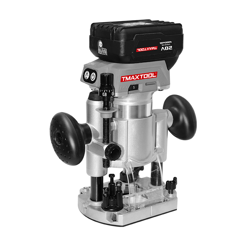 Wood Router
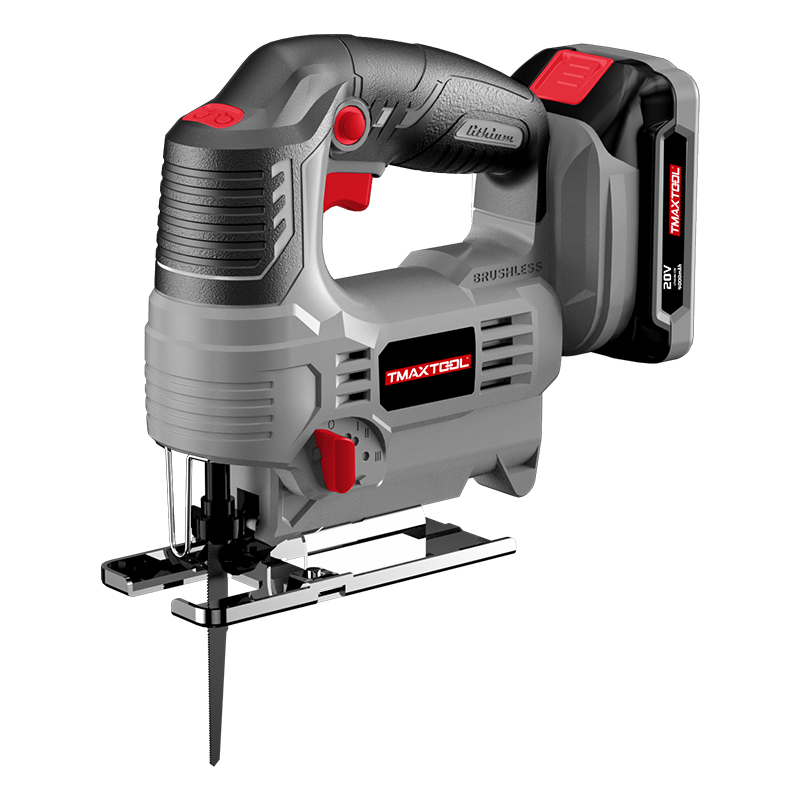 Jig Saw
 Hammer Drill
 Portable Blower
 Orbital Sander
 Marble Cutter
 GARDEN TOOLS
 Battery Chain Saw
 Battery Brush Cutter
 Battery Hedge Trimmer
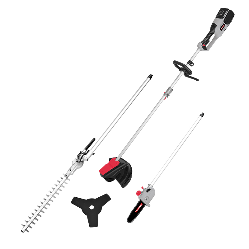 Battery Multi Tool
 Battery Blower
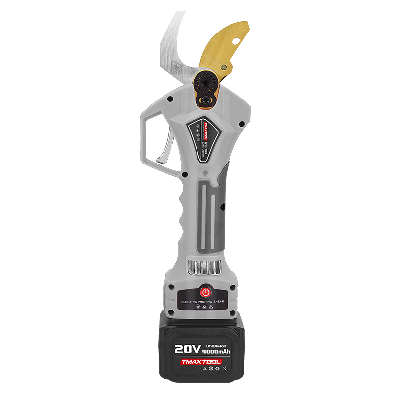 Batter Pruning Shears
 Chain Saw
 Brush Cutter
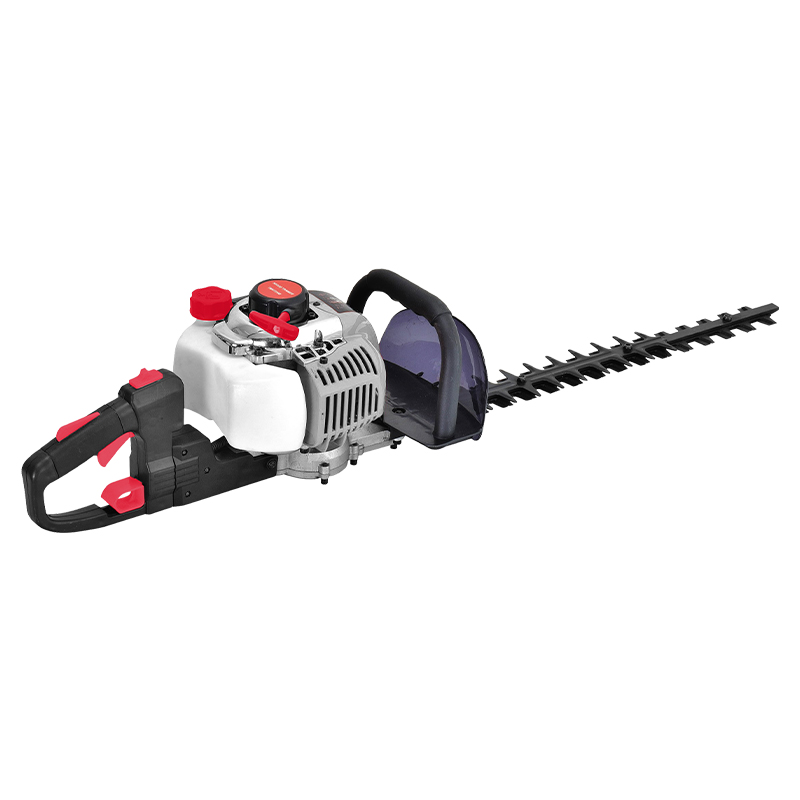 Hedge Trimmer
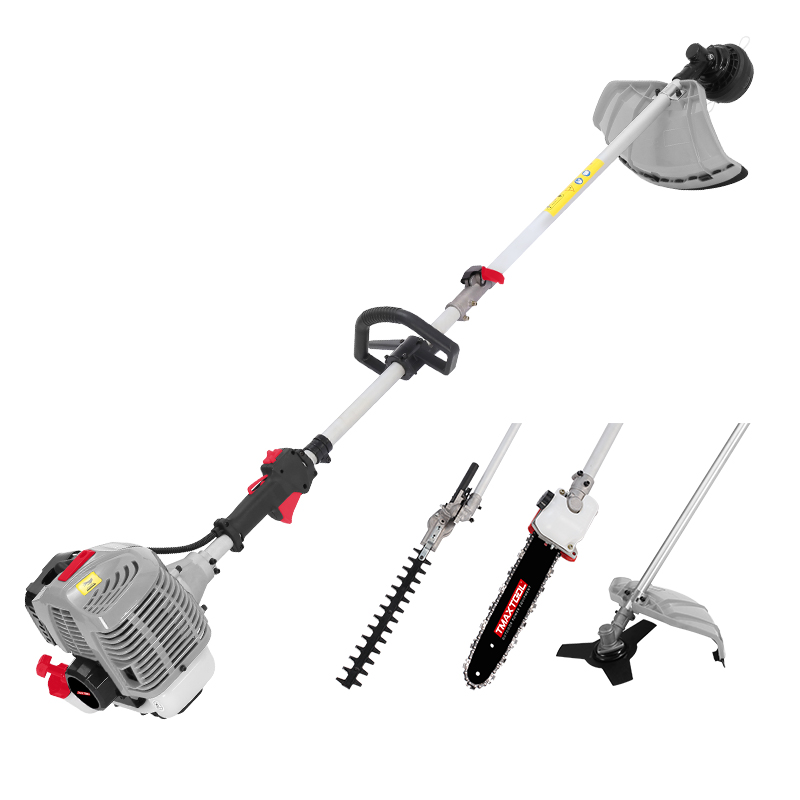 Multi Tool
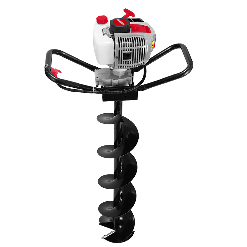 Earth Auger
 Tiller
 Blower
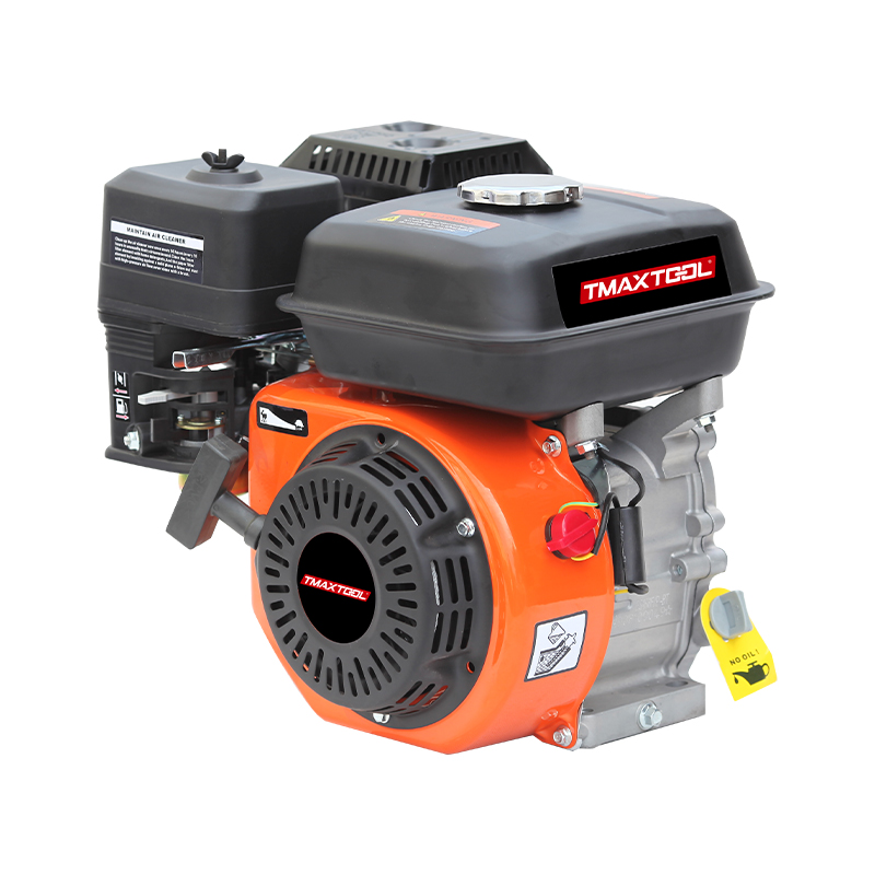 4 Stroke Gasoline Engine
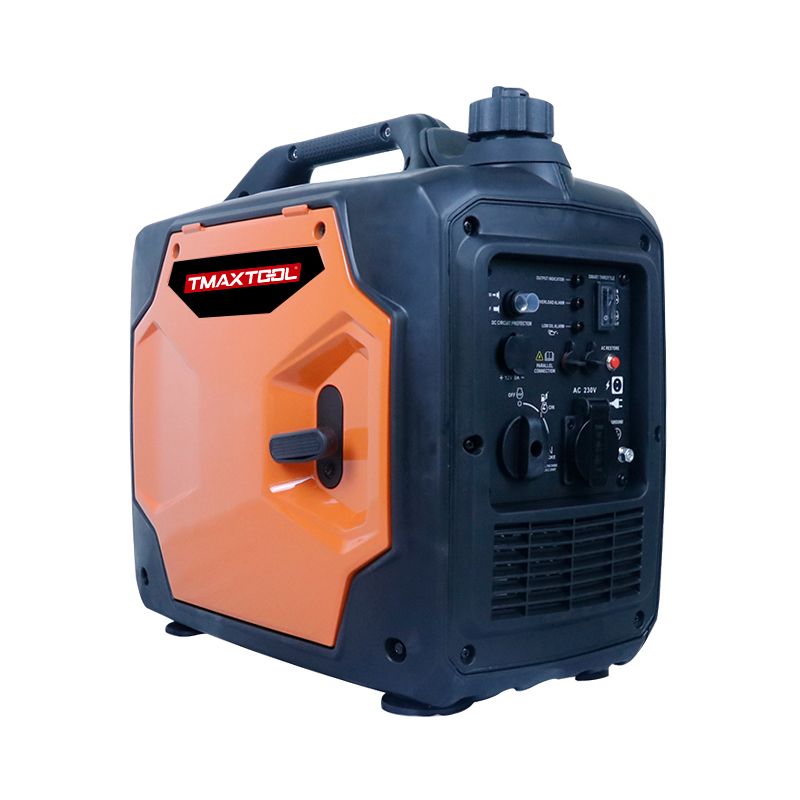 Generator
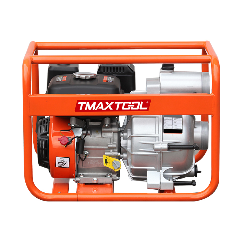 Water Pump
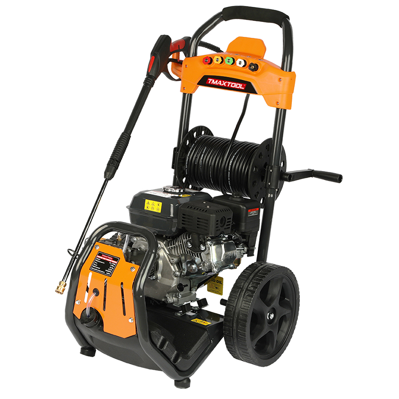 High Pressure Washer
 Wood Cutter
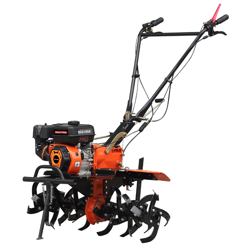 4 Stroke Tiller
 Chain Saw Accessory
 Brush Cutter Accessory
 Earth Auger Accessory
 Protective Equipment Accessories
News


Technical implementation elements of electric pruning shears
Technical implementation elements of electric pruning shears

Nowadays, electric scissors have been widely used in production and life due to their convenience and labor-saving features, such as garden tree pruning, pruning, fruit tree pruning, gardening work, product packaging pruning, and industrial production. In the prior art, electric scissors are hand-held electric tools that use an electric motor as power and drive a working head through a transmission mechanism to perform shearing operations. Composed of cutting tools, etc.
However, when using electric scissors, it is easy for the scissors blade to perform actions not intended by the user. For example, the user pulls the trigger, but the blade does not close, or the trigger has returned but the motor is still rotating and the scissors are still working. wait. This will bring safety risks to the electric scissors or the user. Technical implementation elements: Construct an electric scissors control circuit including: central control unit mcu to receive signals and make instructions;
A switch trigger detection circuit is connected to the MCU and has a first Hall sensor and a first switch. The first switch is installed at the trigger position of the electric scissors for the user to trigger the motor action of the electric scissors in the standby state. The first Hall sensor Connected to the first switch and detecting the opening and closing state of the first switch, and sending the detected first switch signal to the mcu;
a scissors edge closed position detection circuit, which is connected to the mcu and has a second Hall sensor and a second Switch, the second switch is installed in the closed position of the electric scissors, the second Hall sensor is connected to the second switch and detects the opening and closing state of the second switch, and sends the detected second switch signal to the mcu;
Scissors The knife edge opening position detection circuit is connected to the MCU and has a third Hall sensor and a third switch. The third switch is installed at the knife edge opening position of the electric scissors. The third Hall sensor is connected to the third switch and detects the third Hall sensor. The opening and closing status of the three switches, and the detected third switch signal is sent to the mcu;
when the mcu receives the first switch signal, it is low level, and the second switch signal or the third switch signal is alternately at high level and low level. Normally, the MCU determines that the electric scissors are working abnormally and issues a forced power-off command;
When the MCU receives that the first switch signal is high level and the second switch signal or the third switch signal continues to be high level or low level, the MCU determines that the electric scissors are working abnormally and issues a forced power-off command.
Further, the switch trigger detection circuit also includes a first capacitor, a second capacitor, a first resistor and a second resistor. The first resistor and the second resistor are connected in series. One end of the first capacitor is connected to the first resistor, and the other end is connected to ground. One end of the two capacitors is connected to the second resistor, and the other end is connected to ground.
Preferably, the resistance of the first resistor r1 is 10 kiloohms, the resistance of the second resistor r2 is 1 kiloohm, the first capacitor c1 is a 100nf ceramic capacitor, and the second capacitor is a 100nf ceramic capacitor.
Further, the scissors edge closing position detection circuit includes a third capacitor, a fourth capacitor, a third resistor and a fourth resistor. The third resistor and the fourth resistor are connected in series. One end of the third capacitor is connected to the third resistor and the other end is grounded. One end of the fourth capacitor is connected to the fourth resistor, and the other end is connected to ground.
Preferably, the resistance of the third resistor r3 is 10 kiloohms, the resistance of the fourth resistor r4 is 1 kiloohm, the third capacitor c3 is a 100nf ceramic capacitor, and the fourth capacitor is a 100nf ceramic capacitor.
Further, the scissors blade opening position detection circuit includes a fifth capacitor, a sixth capacitor, a fifth resistor and a sixth resistor. The fifth resistor and the sixth resistor are connected in series. One end of the fifth capacitor is connected to the fifth resistor and the other end is grounded. , one end of the sixth capacitor is connected to the sixth resistor, and the other end is connected to ground.
Preferably, the resistance of the fifth resistor r5 is 10 kiloohms, the resistance of the sixth resistor r6 is 1 kiloohm, the fifth capacitor c5 is a 100nf ceramic capacitor, and the sixth capacitor is a 100nf ceramic capacitor.
The implementation of the electric scissors control circuit of the present invention has the following beneficial effects: each detection circuit of the electric scissors control circuit has a corresponding Hall sensor, and the Hall sensor can output corresponding simulations of the corresponding switch action and the opening and closing position of the scissors blade. The signal is given to the MCU, and the MCU can control the rotation of the motor and the action of the scissor blade according to the corresponding analog signals of the switch action and the opening and closing position of the scissor blade. When the electric scissors are in the trigger position and are pulled, the scissor blade is in a stuck state and the trigger is not When the scissors are pulled but in working condition, the MCU determines that the electric scissors are working abnormally and issues a forced power-off command. The purpose is to reduce abnormal movements of electric scissors and provide protection for electric scissors and users.